A number of people have shown interest in making their own Ferrari battery tender / CTEK charge apapter cables (or just buying one - contact me for details if you'd like -
I recently replaced my F430 with a Ferrari 599GTB. I'd included the CTEK charger and adapter when I sold the 430, and so had to make a new cable.
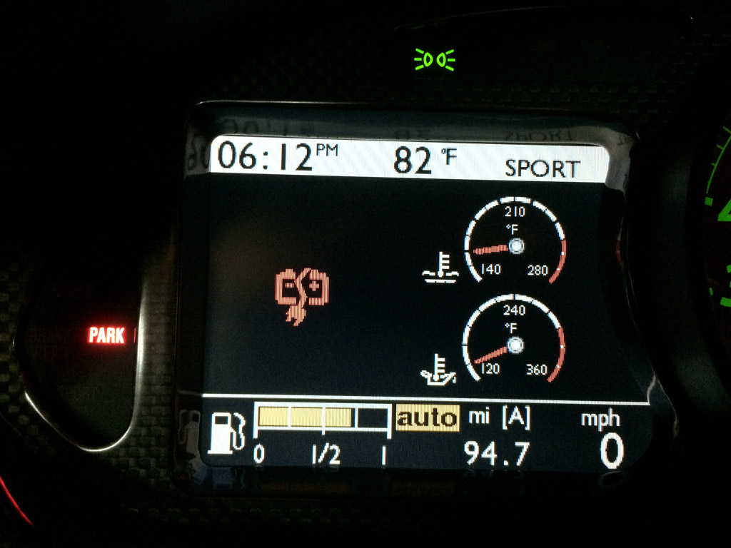
Unsuprisingly it uses the same pinout, and shows the charger connected icon on the LCD.
I ended up also making a few cables for some friends with Ferrari 458, here is a picture:

Seeing as I have now made a fair number of these cables, I figured it was worth making a test harness. I have now have access to a laser cutter / etcher and so made a pretty enclosure:


More images: http://photos.kumari.net/Projects/Ferrarichargecables/
Orginal page:
Ferraris don't much enjoy going out in the snow, and draw a fair amount when powered off. Low voltage conditions lead to all sorts of bizarre electronic gremlins including banks shutting down, weird ECU issues, corruption of the radio presents, check engine lights, etc. This means that keeping them connected to a battery tender when they will be sitting for a few weeks is a really good idea.
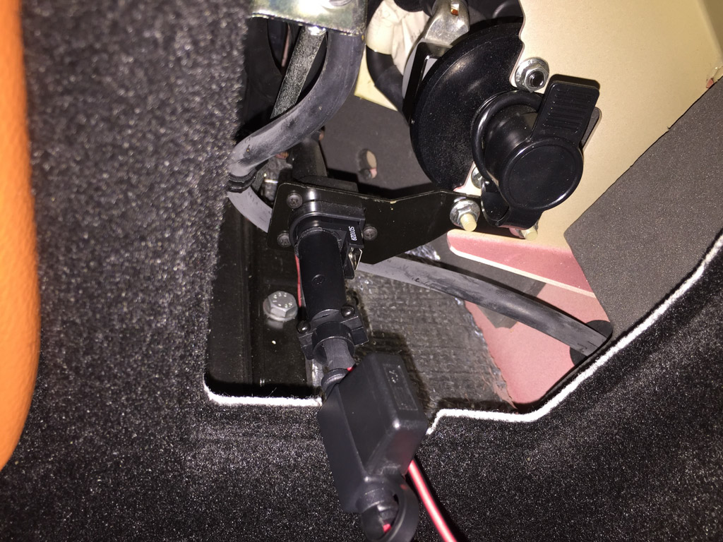
The Ferrari F430 comes with a special connector in the passenger footwell, specifically for connecting a tender. This is useful because it light up a "Charger Connected" icon on the dashboard, and prevents starting the vehicle with the charger connected. Unfortunately the new Ferrari chargers (actually rebranded CTEK ones) do not come with the special connector, and the pinout is not documented anyway.
Initially I simply connected a charing pigtail directly to the battery, bypassing the builtin tender connector, but this lead to two issues:
- I'd sometimes forget that the charger was connected, and start reversing with it still plugged in.
- The fact that there was some functionality that I couldn't access made me annoyed!
So, eventually I decided that I had to figure out how to activate the charger connected lockout.
After some time figuring out and tracing the Ferrari wiring diagrams in the F430 workshop manual I was able to determine that the connector in the footwell really was a tender connection. Of course, it used some odd connector that I'd never seen before, and so I had to remove it to try and figure out both the connector, and, more importantly, the pinout.


The connector is made by Burndy (now part of Souriau) but finding exactly which one of the thousands of connectors that they make took a fair bit of time -- eventually found that it is part of the BANTAMATE II 5000 series, MBG4R1 for the female and MBG4P1 for the male. It uses the Souriau "Trim-Trio" contacts.
After a bit of tracing cables and fiddling with a multimeter I was fairly sure that Pin 2 has to be raised to +12V to activate the charger connected lockout. I built a cable with a few resistors (in case I was wrong I didn't want to draw too much current and kill the ECU) and a switch. I plugged it in, and flipped the switch. There was a reasonably loud click and the charger connected icon came on on the instrument cluster

I then took another CTEK cable, cut off the (crocodile clip) ends and crimped on the Trim-Trio contacts.
The Pinout is as follows:
- PIN_1: +12V (charge)
- PIN_2: +12V (sense)
- PIN_3: Ground
- PIN_4: Not connected.
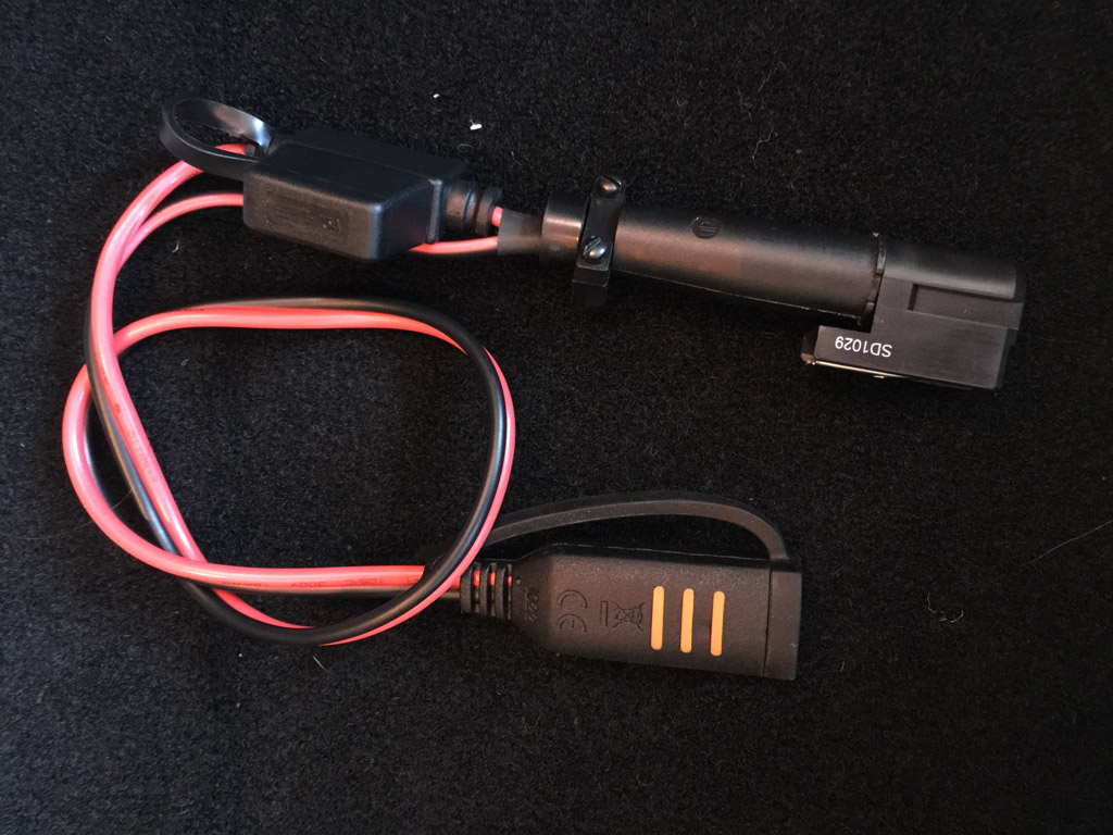
Unfortunately the strain relief boots (MBG4S1) were backordered at Allied, Mouser and DigiKey and so the cable is not as pretty as it could be (eventually they came back in stock, but I couldn't be bothered to remove the pins to install it!).
Some photos of the completed cabe:


More photos in an album, here: http://photos.kumari.net/Projects/Ferrarichargecables/